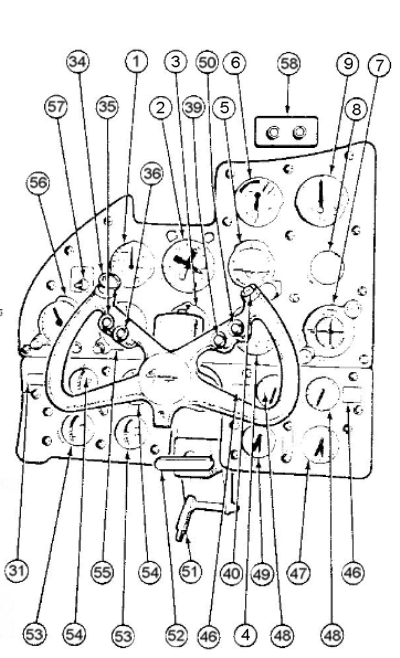
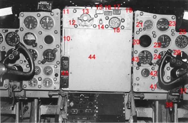
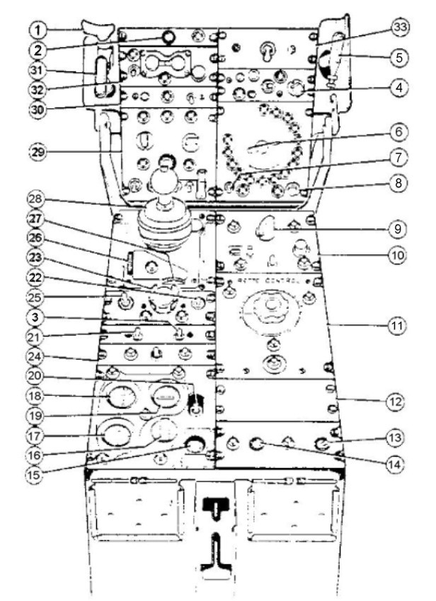
BuiltWithNOF
Cockpit Grumman Tracker

Op deze pagina een verzameling van cockpit gegevens aan de hand van foto’s en afbeeldingen met uitleg van de intrumenten, welke werden gebruikt in de cockpit van de Grumman Trackers. De schema’s met verklaring van de cijfers ontvangen van Ferry Gonggrijp een ex-vlieger op de Grumman Trackers.

(foto 0385) Een overzicht van het centrale instrumenten paneel van de beide vliegers. Links de piloot en rechts de co-piloot. Betreft een Amerikaanse Grumman Tracker. Zie ook het schema en uitleg verder op deze pagina van de MLD Trackers.
Foto Clark A. Cook Sr.

(foto 0386) Opname van de positie van de piloot links in het vliegtuig. Rechts is de plaats van de co-piloot. .
Foto Clark A. Cook Sr.

Pilot’s center instrument panel

(foto 0387)

1.

Pilot’s airspeed indicator.

40

Torpedo-bombs release switch.

2.

Bearing-distance-heading indicator ID-663B/U.

46.

Fuel low level warning light (2).

3.

Pilot’s turn and slip indicator.

47.

Oil pressure indicator.

4.

Pilot’s rate of climb indicator.

48.

Fuel quantity indicator (2).

5.

Vertical gyro indicator (VGI)

49.

Fuel pressure indicator.

6.

Tachometer

50.

Rockets release switch.

7.

Cross pointer indicator ID-249A/ARN.

51.

Pilot’s rudder pedal adjustment handle.

8

Blank plate.

52.

Emergency and parking brake handle.

9.

Manifold pressure gage

53.

Cylinder head temperature indicator (2).

31.

Flight instruments AC power off indicator lights.

54.

Oil temperature indicator (2).

34.

Aileron and elevator trim tabs switch.

55.

Pilot’s altimeter.

35

ICS microphone switch.

56.

Pilot’s radar altimeter indicator ID-257/APN-22.

36.

Radio microphone switch.

57.

Fuel quantity gage test switch.

39.

Signals underwater sound (sus) release switch.

58.

Magnetic chip detector warning lights (2)

(foto 0388a)

(foto 0388) Zitplaats en instrumentenpaneel van de piloot.
Foto ontvangen van Martin Blokker.

Co-pilot’s center instrument panel.

(foto 0389)

10.

Plotting board indicator lights.

28.

Co-pilot’s rate of climb indicator.

11.

Landing check list.

29.

DC voltammeter - left generator.

12.

LF/AD-UHF/DF-OPTI selector switch.

30.

DC voltammeter - right generator.

13.

Ignition switches.

31.

Flight instruments AC power off indicator lights.

14.

Windshield wiper control.

32.

Co-pilot’s instrument lights rheostats.

15.

Fire warning light - left engine.

33.

Searchlight indicator.

16.

Raws warning light, provisions for.

34.

Aileron and elevator trim tabs switch.

17.

Fire warning light - right engine.

35.

ICS microphone switch.

18.

Combination clock.

36.

Radio microphone switch.

19.

Take-off check list.

37.

Co-pilot’s control column disconnect handle.

20.

Milliammeter (mad indicator).

38.

Co-pilot’s rudder pedal adjustment handle.

21.

Accelerometer.

39.

Signals underwater sound (sus) release switch.

22.

Co-pilot’s airspeed indicator.

40.

Torpedo-bomb release switch.

23.

Wheels and flaps position indicator.

41.

Outside air temperature indicator.

24.

Co-pilot’s altimeter.

42.

Carburetor air temperature indicator (2).

25.

Course indicator ID-250/ARN.

43.

Co-pilot’s radar altimeter indicator ID-257/APN-22.

26.

Co-pilot’s turn and slip indicator.

44.

Plotting board PT-434A/ASA-13.

27.

Co-pilot’s gyro horizon indicator

45.

Pilot’s instrument lights rheostats.

(foto 0390a) Voor afbeelding van nr. 44 van het schema zie ook foto 2251 en 2251a verderop.

(foto 0390) Zitplaats en instrumentenpaneel co-piloot.
Foto ontvangen van Martin Blokker.

(foto 2251) Het interieur van een Grumman Tracker welke gestationeerd was op het vliegveld Hato op Curacao tussen 1968 en 1971. Hieronder een detailopname van deze foto.
Foto’s ontvangen van Paul Schulinck.

(foto 2251a) Detailopname van vorige foto. Hierop is duidelijk nr. 44 de ‘Plotting Board’, zoals op het schema weergegeven, te zien. Rechts op de co-pilot stoel is vermoedelijk de LTZV 1 d’Ancona, een van de vliegtuigcommandanten op Hato in die tijd.

Pilot’s folding and diagonal console.

(foto 0391)

1.

G-Limiter manuel release handle.

18.

Aileron trim tab position indicator.

2.

Floatlight release button.

19.

Elevator trim tabs position indicator.

3.

Raws test switch.

20.

Elevator trim tabs stand-by switch.

4.

Plotting board control (local) ASA-13.

21.

Fire detect test switch.

5.

Torpedo manual release handle.

22.

Automatic pilot power switch.

6.

Sonobuoy control knob.

23.

Automatic pilot clutch switch.

7.

Sonobuoy master switch.

24.

UHF/VHF control panel.

8.

Sonobuoy light test switch.

25.

Automatic pilot altitude control switch.

9.

Console lights control rheostat.

26.

Automatic pilot pitch trim wheel.

10.

Signals underwater sound (sus) control panel.

27.

Automatic pilot bank trim wheel.

11.

Retro marine marker ejector control box.

28.

Automatic pilot controller.

12.

Blanking plate.

29.

Master armament control panel.

13.

Stall warning test switch.

30.

Roll stabilization control panel MF-1 compass.

14.

Single engine rudder assist switch.

31.

Automatic pilot manual release handle.

15.

Elevator trim tabs emergency stop switch.

32.

Tacan control ARN-21.

16.

Rudder trim control.

33.

Rocket stepping interrupter box.

17.

Rudder trim position indicator.


(foto 0392) Opname van een deel van de overhead console.

(foto 0393)

1.

Fuel selector valve control - left engine.
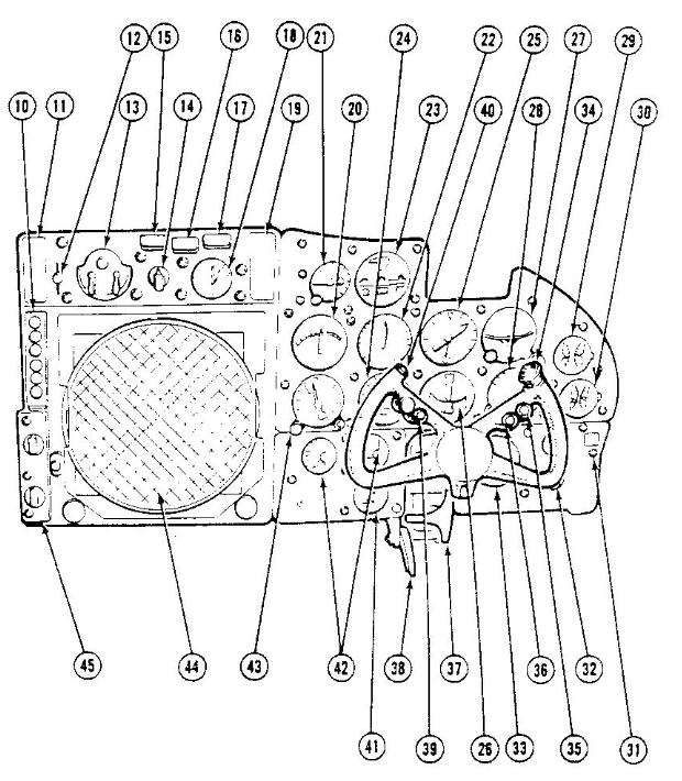
26.

Propeller controls.

2.

Life raft release handle.

27.

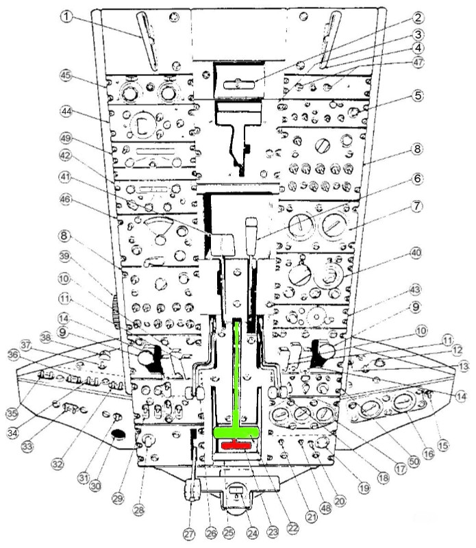
Landing gear control handle.

3.

Wing fold control panel.

28.

Console lights control.

4.

Fuel selector valve control - right engine.

29.

Master electrical power panel.

5.

Exterior lights control panel.

30.

Landing gear solenoid override.

6.

Arresting hook control handle.

31.

Pitot heat switch.

7.

Hydraulic system pressure gages (2).

32.

Auxiliary fuel pump switches (2).

8.

ICS and radio control panel (AIC-8).

33.

Oil dilution switches (2).

9.

Propeller feathering button and indicator light (2).

34.

Carburetor air switches (2).

10.

Emergency hydraulic oil shut-off switch (2).

35.

Cowl flaps switches (2).

11.

Fire extinguisher switch (2).

36.

Oil cooler doors switches (2).

12.

Propeller de-icing control switch and indicator light.

37.

Primer switch.

13.

Windshield anti-icing and washing switch.

38.

Starter switch.

14.

Emergency fuel and oil shut-off switch (2).

39.

Throttles friction control.

15.

Wing and tail de-icing control switch.

40.

UHF transmitter-receiver control panel (ARC-27A).

16.

Wing and tail de-icing pressure and suction gages.

41.

Wing flaps control handle.

17.

Torpedo bay and sonobuoy temperature gages.

42.

HF transmitter-receiver control panel (ARC-120).

18.

Mixture controls.

43.

Range receiver control AN/ARC-5.

19.

Air conditioning heater rheostat.

44.

IFF control panel (APX-6, -6B).

20.

Air conditioning heater control switch.

45

SIF control panel (APA-89).

21.

Ground ventilation control switch.

46.

Radio compass control (ARN-6).

22.

Throttles.

47

Anti-collision lights switche (2).
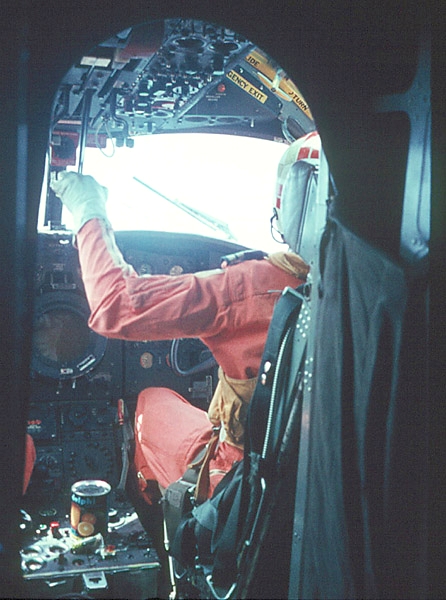
23.

Catapult grip. (zie ook foto onder)

48.

Heater temperature control switch.

24.

Stand-by magnetic compass

49.

VHF transceiver control panel

25.

Gust lock control handle.

50.

Compass controller (MF

(foto 0394) Kijkje in de cockpit van een Grumman Tracker met rechts de co-piloot die met de linkerhand de “CATGRIP” vast heeft. We zien ook een deel van het overhead console.
Foto Vereniging Oud-Valkenburg. Fotograaf Stijn Coccoris.

Zie voor meer info en foto’s mbt de cockpit ook:

Grumman Tracker 160 (deel 1 t/m 4);

Engine Contral Assembly;

Uitleg cockpit check.


Terug naar Tracker index.


[Home] [Indeling site] [Welkom aan boord] [QH-1 '46-'48 index] [R81 '48-'55 index] [R81 '58-'68 index] [Bemanning index] [Anekdotes index] [Opleidingen index] [Vliegdienst index] [Algemeen index] [Vliegrol aan boord] [Untitled664] [S2A Tracker index] [Avenger] [Sea Otter] [Sea Hawk] [Firefly] [Seafury] [Sikorsky] [Reizen & havens index] [Gebeurtenissen] [Gastenboek] [Contact]